Independent connections
QSM-2D uses synchronized comb actuation within each independently controlled, two-axis mirror.
Explore QSM-2D ↗
Our patented synchronization technology combines comb actuation force for independently controlled OCS mirrors, or mirror apertures for LBS display and LiDAR.
A mechanical coupling structure connects mirror elements at matched leverage points. As one mirror rotates, motion is transmitted so the mirrors rotate together.
Smaller moving elements reduce individual inertia. Multiple hinges and anchors provide distributed heat paths into the substrate. Equal-angle motion preserves scan geometry across the array.
Synchronized-aperture concept only; QSM-2D OCS mirrors are individually controlled. Element count and motion do not represent a product specification or optical simulation.
See the synchronized-aperture approach in device footage.
The mirror elements move together to combine their optical area. For OCS, we apply synchronization to comb actuators instead, leaving each QSM-2D mirror independently controlled.
See independent OCS mirror motion ↗Close-up footage of a synchronized mirror array. Small mirror elements share motion to form a larger effective optical aperture—the principle used for display and LiDAR scanners. QSM-2D uses synchronized comb actuation with independent mirror control.
Visual demonstration · No audioEven coupled mirrors can have small angle differences because of device-to-device variation. Non-linear springs and limiters shape the torque–angle response, creating a preferred operating band where the elements settle into a shared dynamic state.
Well-placed stops help the array maintain unified motion when disturbed. The aim is consistent amplitude and phase across the elements, improving optical uniformity and reducing the calibration burden under manufacturing and environmental variation.
For QSM-2D optical circuit switching, synchronization happens inside each mirror’s drive mechanism. Each OCS mirror remains independently controlled.
Groups of comb-drive actuators are mechanically linked so their forces add while unwanted motion is suppressed. The coupling network increases stiffness against lateral and out-of-plane disturbances, supporting high available torque and low-voltage actuation while helping resist collisions and drift.
The actuator array and mirror array are distinct. Several actuator units can drive one mirror element, and their relative sizes can be selected for the application. Small moving mirror elements reduce inertia; an actuator array can also drive a single larger mirror when the optical design requires it.
Related actuator-array patents are pending. This page summarizes published work and ongoing R&D; detailed schematics and application-specific information are available under NDA.
Explore independently controlled OCS mirrors ↗In this demonstration, each mirror is driven by eight synchronized comb actuators. The changing colors come from diffraction: the comb fingers act like tiny optical gratings, directing different wavelengths toward the camera as they tilt. This is a demonstration configuration, not a fixed actuator count for every product.
Visual demonstration · No audioSmall moving masses reduce inertial loads. Multiple hinges and anchors provide heat paths into the substrate, while mechanical coupling preserves shared motion in synchronized-aperture arrays.
Original side-by-side test footage. The published demonstration describes approximately 4 g RMS shaker exposure, with steady reflected beam spots from the inSync array. The comparison applies to the devices and conditions shown.
Visual demonstration · No audio| Test | Published conditions |
|---|---|
| Vibration demonstration | Approximately 4 g RMS shaker exposure |
| Half-sine shock | Approximately 1,500 g; three shocks in each ±x, ±y and ±z direction |
| Operating mechanical tests | Pothole shock referencing GMW3172 and random vibration referencing ISO 16750-3 |
| Temperature cycling | −40°C to +125°C; 1,000 cycles |
| Heat and humidity | 85°C / 85% relative humidity; 1,000 hours |
| High-temperature operation | 125°C; test duration available with the underlying report |
The original footage shows the shock-test setup. The published test description reports approximately 1,500 g half-sine shocks, three shocks in each of the ±x, ±y and ±z directions, with the tested devices remaining mechanically intact and functional.
Visual demonstration · No audioThese are reported tests on specific devices and configurations, not a certification or an operating rating for every product. In particular, QSM-2D’s specified operating range is −40°C to +85°C. Ask us for the test data relevant to your application.
The published operating-test figure documents high-temperature operation. Together with shock, vibration and environmental testing, it provides context for discussing reliability requirements for a particular device and configuration.
We can discuss your operating band, aperture, coatings and control interface, and review detailed test conditions under NDA.
Discuss qualification requirements ↗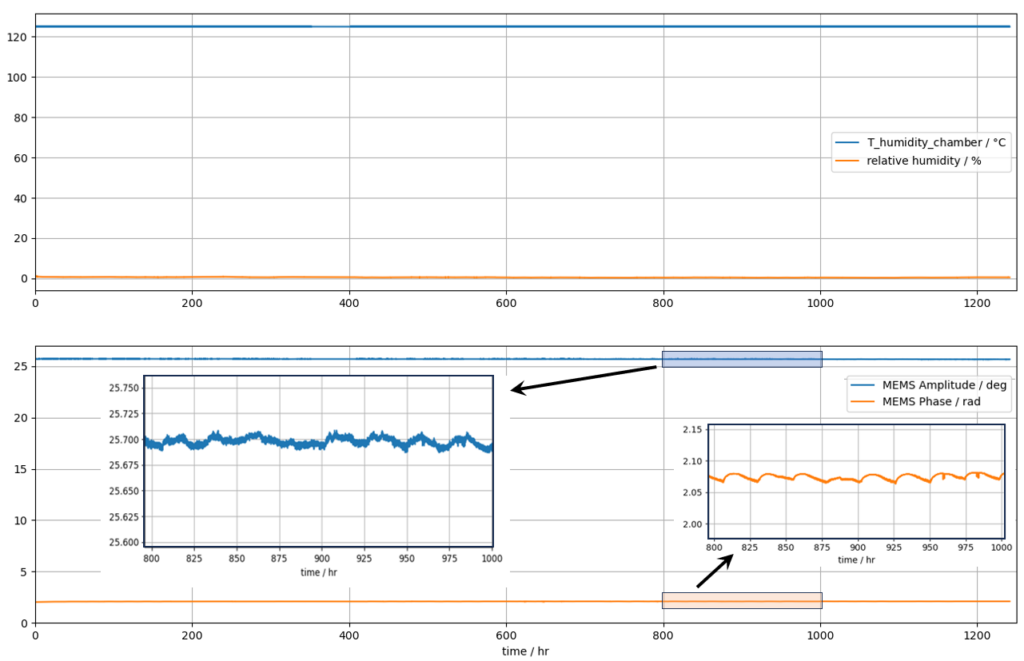
Configure synchronized actuators or synchronized apertures around the motion your system needs.
QSM-2D uses synchronized comb actuation within each independently controlled, two-axis mirror.
Explore QSM-2D ↗IFM and ISM combine small mirror elements into resonant synchronized apertures for displays, LiDAR and optical scanning.
Explore IFM ↗QSM-1D combines synchronized mirror and actuator arrays for single-axis positioning and step-and-settle scanning.
Explore QSM-1D ↗