Force through synchronization
Coupled comb-drive actuator groups add force and stiffness for controlled two-axis motion.

Individually controlled, two-axis MEMS mirrors for optical circuit switching, driven by synchronized comb actuators.
Prototypes shown · Open for NRE contracts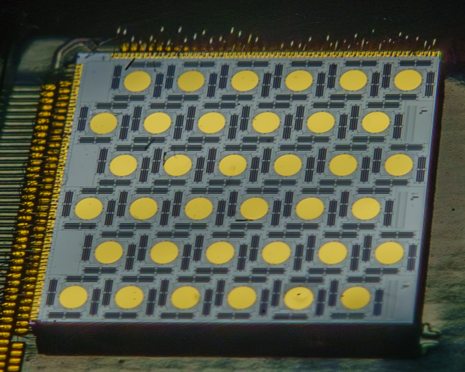
Each mirror steers independently. Within each mirror’s drive mechanism, mechanically coupled comb-actuator groups combine force and stiffness. The architecture is designed for low-voltage, high-reliability actuation, deterministic positioning and stable holds for port-to-port alignment.
Coupled comb-drive actuator groups add force and stiffness for controlled two-axis motion.
The footage shows a 36-mirror prototype. A 168-mirror array is planned and remains under development.
NRE (non-recurring engineering) development engagements are underway, and we welcome new contracts. Aperture, coating, package and control interface can be scoped around your optical switching system.
Explore QSM-2D through device and optical demonstrations. Refer to the technical overview below for specifications and development status.
View specifications ↓Watch the changing orientations across the prototype array. The mirrors can steer independently rather than moving together as one optical aperture.
Visual demonstration · No audioA red laser illuminates the 36-mirror array. Reflected spots on a screen show two-axis positioning, followed by individual elliptical trajectories. Mist makes the separate beams visible in the final sequence. This illustrates motion, not a measured OCS system specification.
Visual demonstration · No audioThe devices shown are prototypes. Drift is a measured result under the stated indoor conditions; yield is typical. Discuss your application’s specifications and NRE development requirements with us. The four-quarter package image illustrates a 144-mirror concept, not the planned 168-mirror array. Response estimates on the original site are not treated as measured specifications here.
| Parameter | Value / notes |
|---|---|
| Development status | Prototypes shown; NRE development engagements underway; accepting new NRE contracts |
| Steering | Two-axis, quasi-static |
| Maximum mirror angle | ±7.5° mechanical on each axis |
| Measured angular drift | <0.002° mechanical over two weeks in an indoor environment without air conditioning |
| Operating temperature range | −40°C to +85°C |
| Typical mirror yield within a die | >95% — proportion of mirrors in a die that meet the defined specifications |
| Demonstrated array | 36 mirrors |
| Planned array | 168 mirrors — under development |
| Published drive-voltage target | <85 Vpp |
| Aperture and settling | Application-specific; discuss requirements |
| Detailed data | Available under NDA |
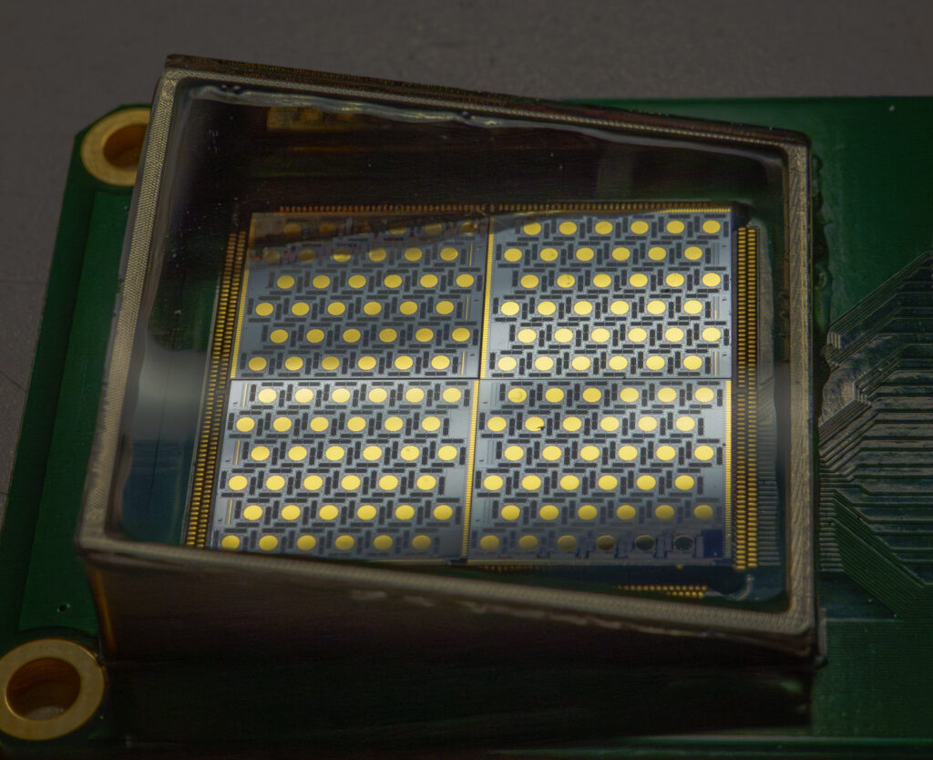
Share the aperture, scan pattern, wavelength band and operating environment your system needs. We can discuss the configuration and available technical details.
Contact the team ↗