Collimate the transmit beam
A larger effective aperture supports tighter collimation and lower transmit-beam divergence, helping the optical system pursue its range and angular-resolution targets.

Large-aperture resonant MEMS scanners for LiDAR and general optical scanning, available in 1D and hybrid 2D configurations.
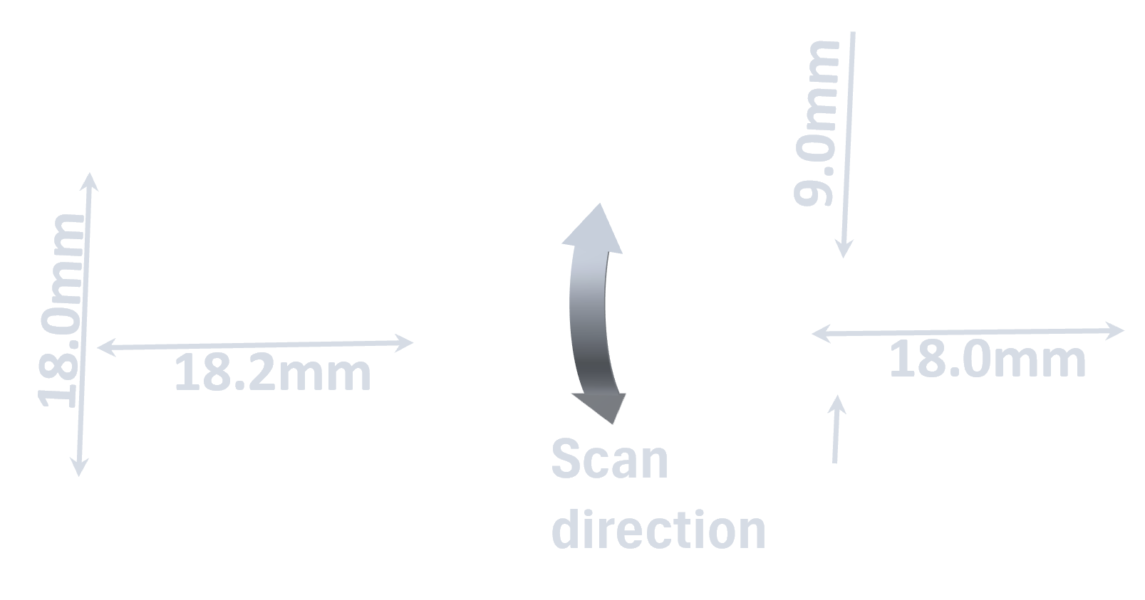
ISM150 / ISM290 configurations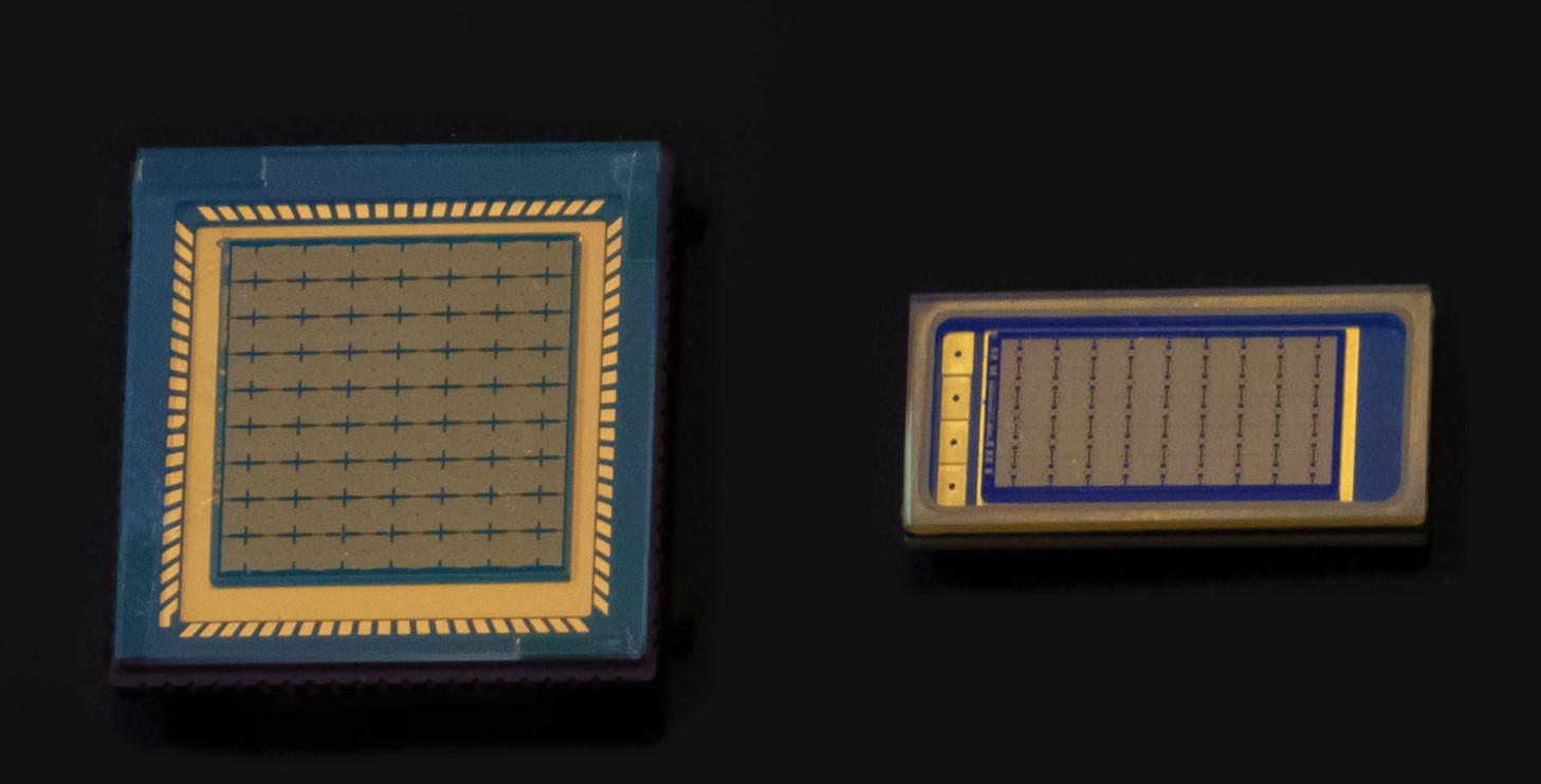
ISM combines the optical area of many small mirrors for LiDAR transmit and receive paths. Synchronizing their angles preserves scan geometry while keeping individual moving elements small. Multiple hinges and anchors carry heat into the substrate, supporting the mechanical and thermal design of a scanning system.
A larger effective aperture supports tighter collimation and lower transmit-beam divergence, helping the optical system pursue its range and angular-resolution targets.
On the receive path, a larger collecting area helps gather more reflected light, improving the available signal for the receiver and its signal-to-noise budget.
Small mirror elements keep rotational inertia low. Synchronized motion supports consistent scan geometry and timing, while multiple heat paths help manage optical power.
This is one possible configuration of the scanning system: TX/RX → MEMS → polygon → screen. The ISM mirrors provide the fast scan first; a rotating polygon then adds the slow axis. Differently angled facets shift successive sweeps into different elevation bands.
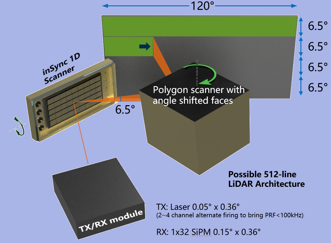
One possible scanning-system configuration, based on the illustration below. Angled facets produce four slightly overlapping bands; same-angle facets use a larger MEMS sweep to cover a similar overall field. The screen pattern and approximately 90° horizontal sweep are schematic. Motion, dimensions, mirror count and scan density are illustrative. The beam depicts the transmit path; receive optics are omitted.
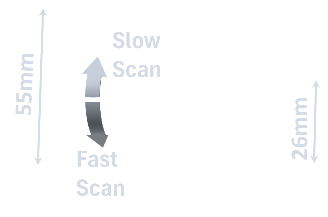
Compare with the original design illustration ↓A compact architecture places the hybrid 2D ISM directly in front of the transmitter and receiver module. Its resonant fast axis and quasi-static slow axis define the scanned field, reducing the need for bulky relay optics.
One suggested configuration uses an edge-emitting laser with its fast axis oriented vertically: narrow vertical divergence controls elevation, while a few degrees of horizontal divergence illuminate the region sampled by the receiver. A horizontally oriented detector array collects several points per pulse as the scan progresses.
Matching the illuminated region to the receiver’s sampled region is intended to reduce ghost responses from bright objects reaching neighboring detector pixels. Beam shape, detector geometry and scan timing must be designed together.
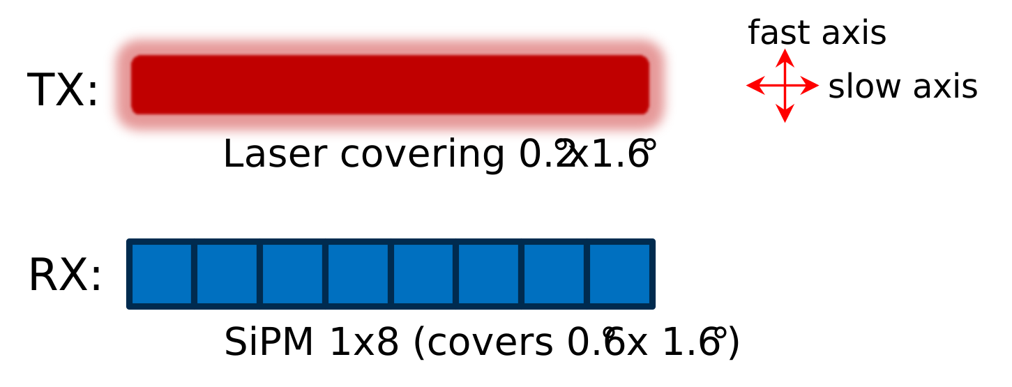
When the mechanical layout or cost requirements favor it, pair a 1D ISM resonant fast axis with a polygon scanner providing the slow axis. This creates a two-dimensional scan while keeping the transmitter/receiver module separate from the scanning elements.
A 256-line reference concept uses an approximately 0.1° × 3.4° transmit beam and a 1 × 32 silicon photomultiplier (SiPM) receiver array. Sampling multiple horizontal spots per pulse can increase effective line and point-cloud density, subject to the optics and timing budget.
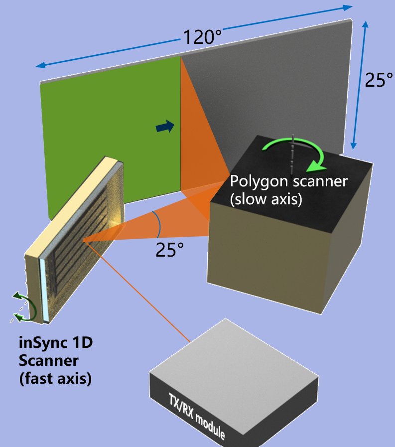
A further option uses a polygon with differently angled faces. Successive facets shift the scan into separate elevation bands, combining the ISM fast axis with a wider overall sampling pattern.
The illustration proposes a possible 512-line architecture, with example transmitter divergence, receiver geometry and alternating laser-channel timing. It is a starting point for system design; the achievable line count depends on the complete optical and timing configuration.
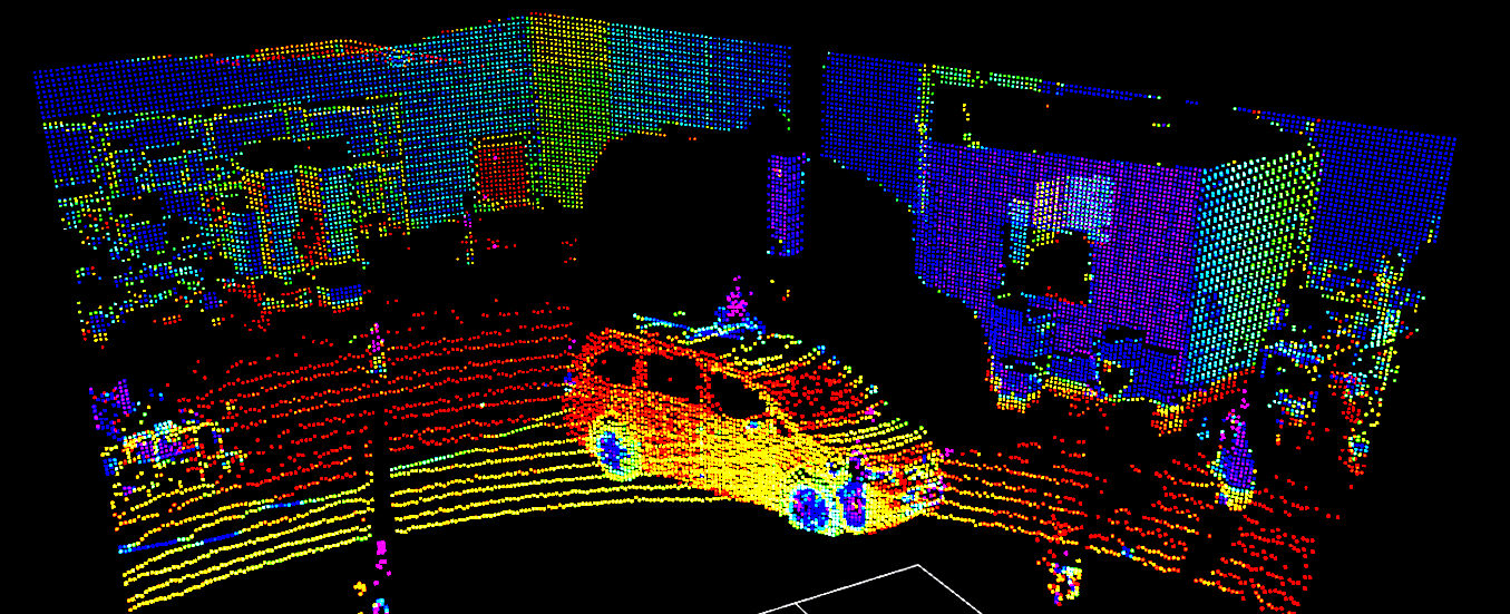
Our published reference LiDAR design is described as offering resolution equivalent to a 250-line mechanical LiDAR and a 200 m effective range. The point cloud illustrates the reference-design discussion.
These figures describe the complete reference system. Discuss its transmitter, receiver, optics and test conditions with us when assessing suitability for your application.
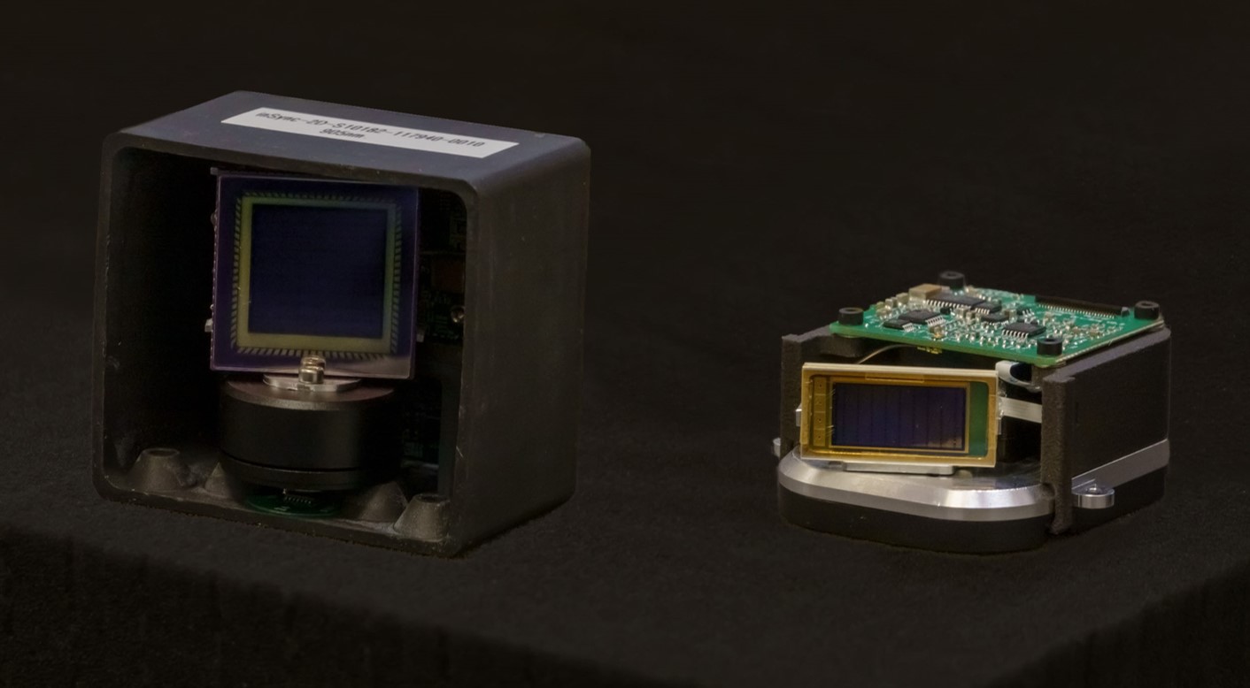
Explore ISM through device and optical demonstrations. Refer to the technical overview below for specifications and development status.
View specifications ↓A laser scan traces a pattern on a wall before the camera shows the scanner setup. This demonstrates optical scanning; it is not a LiDAR ranging or point-cloud demonstration.
Visual demonstration · No audioWe can provide application notes on transmit/receive geometry, divergence choices and reference designs. Share your field of view, sampling pattern and integration requirements.
Coordinate laser divergence, aperture and detector-array orientation so illumination and collection cover the intended region.
Choose hybrid 2D or MEMS-plus-polygon scanning around the mechanics, then coordinate pulses and detector sampling with the scan.
Discuss coatings, thermal requirements, shock and vibration conditions. The Technology page includes the published reliability demonstrations.
Values summarize the published ISM150 / ISM290 tables. Performance depends on optics, drive and environment. Hybrid 2D configurations and application notes are available on request.
| Parameter | Value / notes |
|---|---|
| Effective aperture — ISM150 / ISM290 | 150 / 290 mm² |
| Typical frequency — both models | 2,000 Hz |
| Typical optical scan, p-p — ISM150 / ISM290 | 25° / 15° |
| Maximum optical scan, p-p — ISM150 / ISM290 | 30° / 20° |
| Typical drive power — ISM150 / ISM290 | 0.5 / 0.75 mW |
| Typical drive voltage — ISM150 / ISM290 | 125 / 70 Vpp |
| Typical reflected-beam divergence | 1 mrad at 905 nm |
| Typical reflectivity | 97%, 905–1550 nm |
Share the aperture, scan pattern, wavelength band and operating environment your system needs. We can discuss the configuration and available technical details.
Contact the team ↗